Welcome to Our Garage
Daytona Coupe, 289 and 427 Cobras
-01 -
Cobra Fabrication -
Tools and Equipment -
Traditional Methods
Introduction
While working on my Cobras over the years, I have collected a number of speciality tools to make building, fabricating and maintaining the cars easier. In this section of the site, my intent is to share details of some of these tools. For those who would also enjoy building the tools for their own projects, I have included free downloadable PDF file documentation providing information on how I built some of the tools and machines currently in my shop.
Not all of this equipment was necessary for building my cars. As a matter of fact, many of the tools have been acquired after most of the heavy fabrication on the Cobras was completed. However, like most "equipment" it is a question of balancing time versus money. The correct machine or tool can make fabrication tasks much easier and faster. However, I understand that as a hobbyist, it is a question of where to spend the available funds; on the tools or on the project.
I hope this section provides some insight into equipment that can assist a fabrication project such as the Cobra.
English Wheel
One of the indispensable tools that I used for making many of the aluminum panels on my Coupe is the English Wheel. John Glover, a master with the English wheel, developed a wheel design that used a fabricated frame rather than the more traditional cast iron frame design. The attached sketches are John's original design and with a few minor document the tool that I built and used on my project.
Click on the following "English Wheel Construction sketches" text for a PDF copy of the sketches.
Click here for English Wheel Construction Sketches
I have also added a few short video clips of John Glover demonstrating the use of the wheel in the video section of this web site.
Click on the following "John Glover English Wheel video" text to jump directly to my Videos page, then scrol down the page to the secction titled "Example video from an expert" for short video segiment.
Click here for John Glover English Wheel video
Bracket Bending Brake
I recently came across some of my old sketches for a homemade bracket bending brake that I would like to share.
I built this tool in 1980 while I was fabricating the chassis for my 289 Cobra. The original Cobra chassis is a very basic ladder design which uses mild steel round and square tubing and flat plate of varying gauges. Making precise, uniform bends in the heavier gauge flate plates for Cobra brackets required a suitable bender. It therefore seemed prudent to have my own bending brake capable of fabricating the required bends. I am sure that there were suitable plate brakes available (and more importantly affordable to a hobbiests) in the 1980 time frame. However, I elected to build my own. I would suspect that my logic at the time was something like ".....how hard could it be?"
The design shown in the sketches was based on the material that I had available and the size of the Cobra brackets that needed to made. It now looks a little crude, but I can say that the tool is still very functional and I use it routinely to bend mild steel up to .125" thick. If I had to do it again, I would make a few modifications to the design including:
-
Make the bed slightly wider (some of the required Cobra brackets were a little to wide for this tool to bend.)
-
Add a stop for precisly repeating bends.
-
Use smaller bolts and taped holes in the hold down blocks (versus the 1/2" diameter bolt and nut.)
-
A more refined design for adjusting the bending leaf set back (presenty shims are used to adjust the spacing)
-
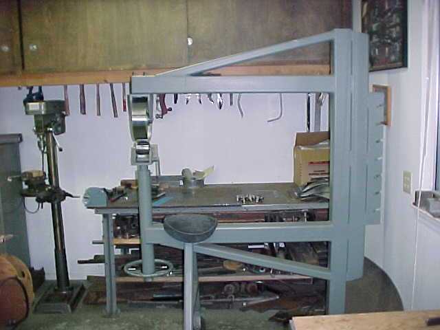
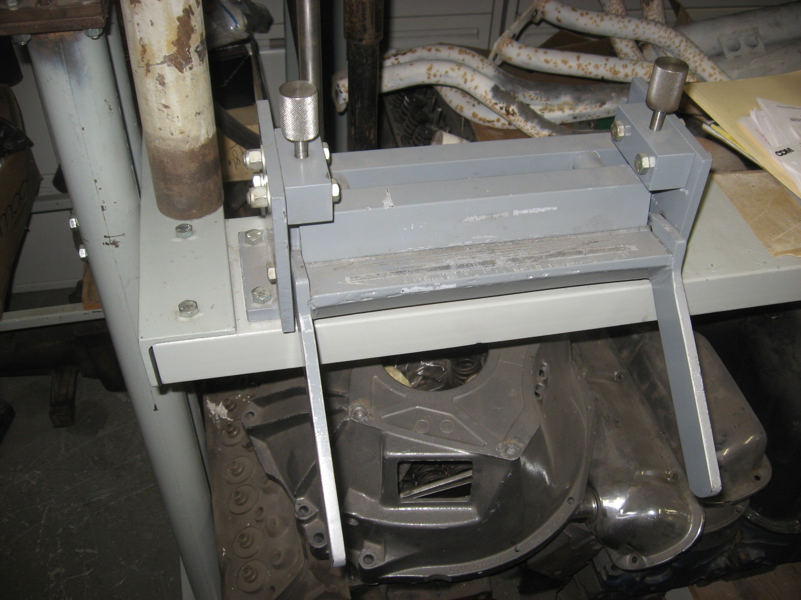
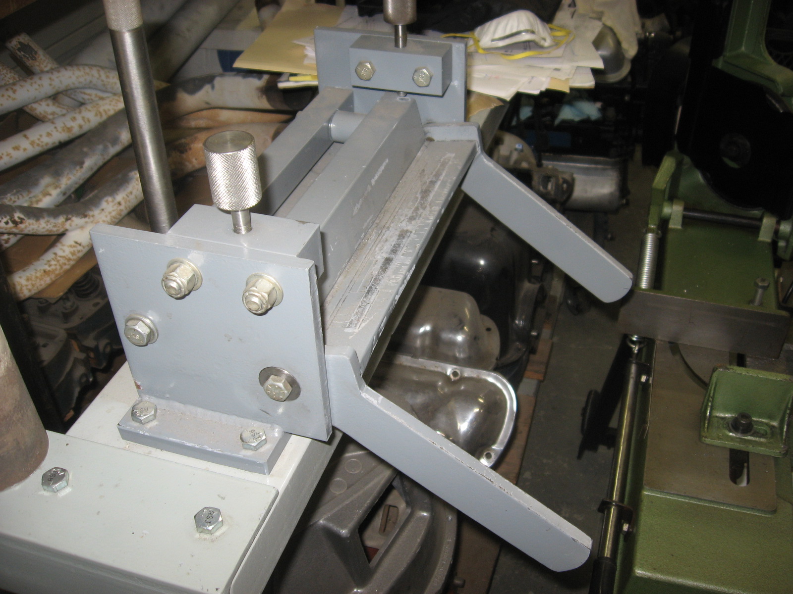
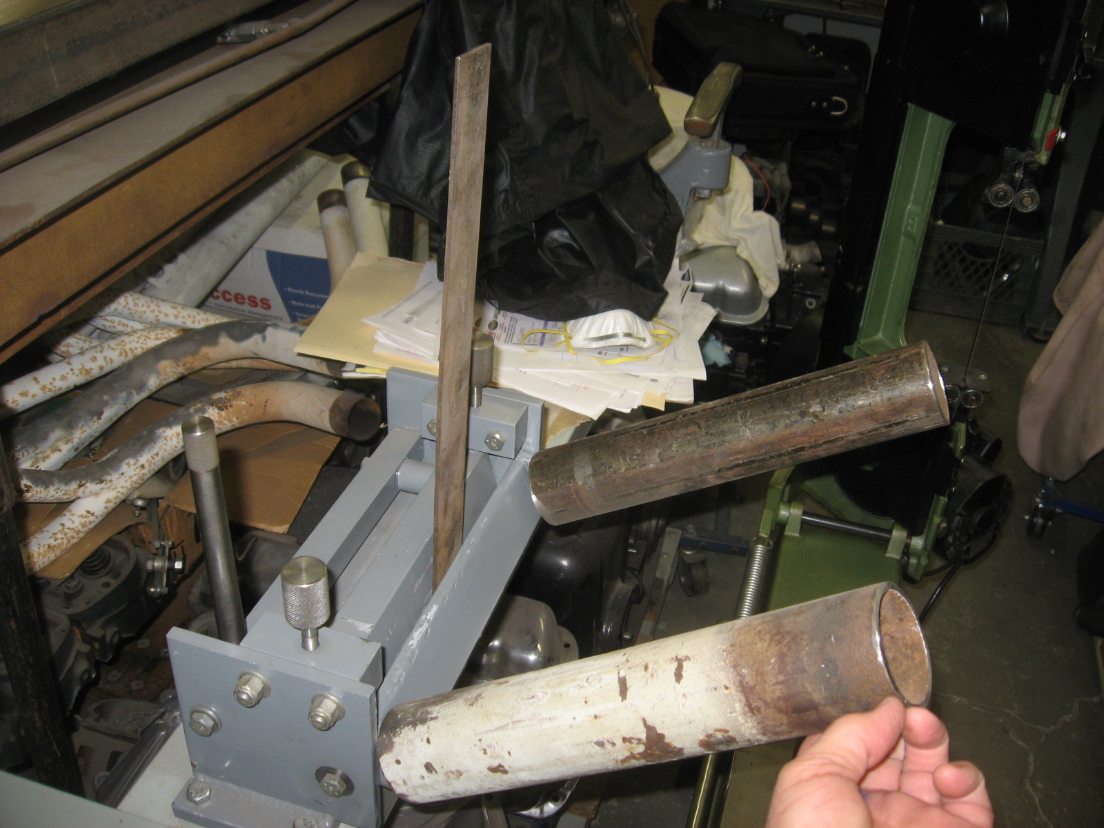
A better way of attaching extensions to the bending arms (presenly I simply slip a short section of pipe over each arm - as shown in the photo below).
The sketches were initially prepared so that I had an idea of the material that was needed for the project and how it would need to be machined and fit together. They were never completely finalized but all of the basic information presently shown on the sketches are very close to the tools present as-built condition. I appologize for the poor quality of the sketches and the PDF scans, but when used in combination with the three photos of the finished brake (below), they will make more sense.
Click on the following "Bracket Bending Brake construstion sketches" text to download a PDF copy of the sketches.
Click here for Bracket Bending Brake Construction Sketches
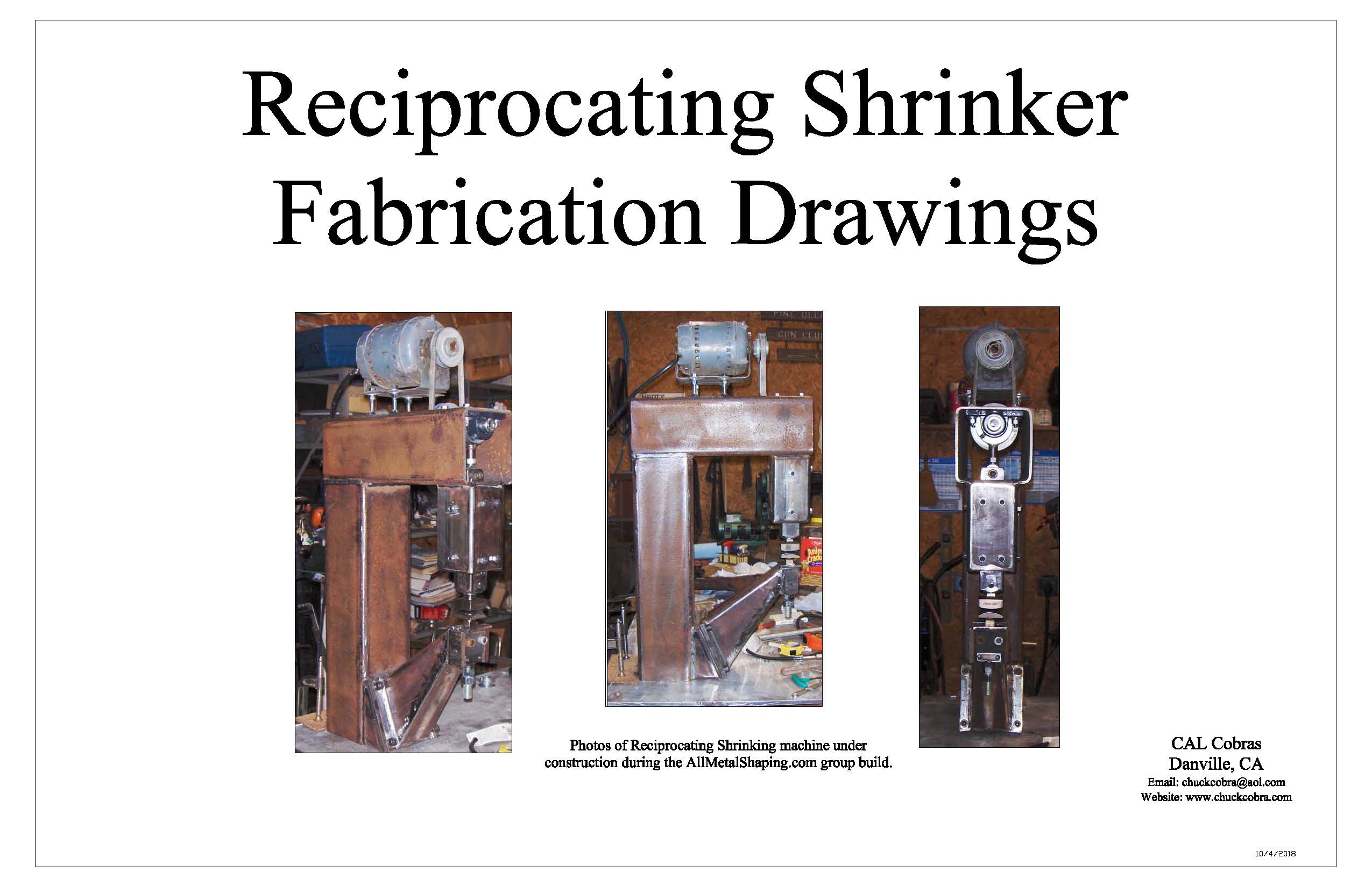
Reciprocating Shrinker
Shrinking of aluminum panels can be done by many methods and there are many manual tools to do this task including: tucking forks, stump shrinking, etc. Many of these tools can be easily made by the hobbiest.
Alternatively, power operated shrinking equipment can certainly save a lot of time when a lot of shrinking is needed on a larger project. However, even hobby grade equipment can be quite expensive to purchase.
Power operated shrinking can be done with either pneumatic or electric motor drive and both have advantages and disadvantages.
Researching the various powered shrinkers on line, I found a web site (AllMetalShrinkers.com) dedicatd to promoting metal shaping techniques as well as the sharing of ideas and craftsman skills. A number of years ago, several members of the group colaborated to build a motor driven shrinker as a group project. Several aspects of their machine that intreiged me were: (1) it was designed to be builty at a minimal cost and (2) it required minimal machining work to build. Another aspect of the machine that I found compelling for my needs was it was powered by an electric motor. To my way of thinking, driving a shrinker directly from a motor is more effecient because it eliminates the air compressor required by a pneumatic drive shrinker. The final reason that I find this machine desirable is it's compact design. The design appears to be heavy enough to make quick work of any shrinking but is also compact enough not to clutter up a small shop.
A lot of information is provided on their web site about the building of the machine and I encourage those looking for a shrinker of this type to check out the group.
As I studied the information available on the Allmetalshapers site, it became obvious to me that although most of the details for constucting a similar recipricating shrinker was provided, it was spread over a number of pages. I have used the information available to developed a comprehensive set of CAD drawings detailing the machine and it's components in one document.
Click on the following "Recipricating Shrinker Construction Drawings" text to download a PDF file.
Click here for Recipricating Shrinker Construction Drawings
Although I have not constructed this machine yet myself (it is just a question of setting aside some time to tackle the project) I have little doubt that it will make a very nice addition to any small shop that wants to move up to a powered shrinking mnachine. Since my machine is yet to be built, the cover sheet of the drawings included below provides a basic idea of what the machine looks like.
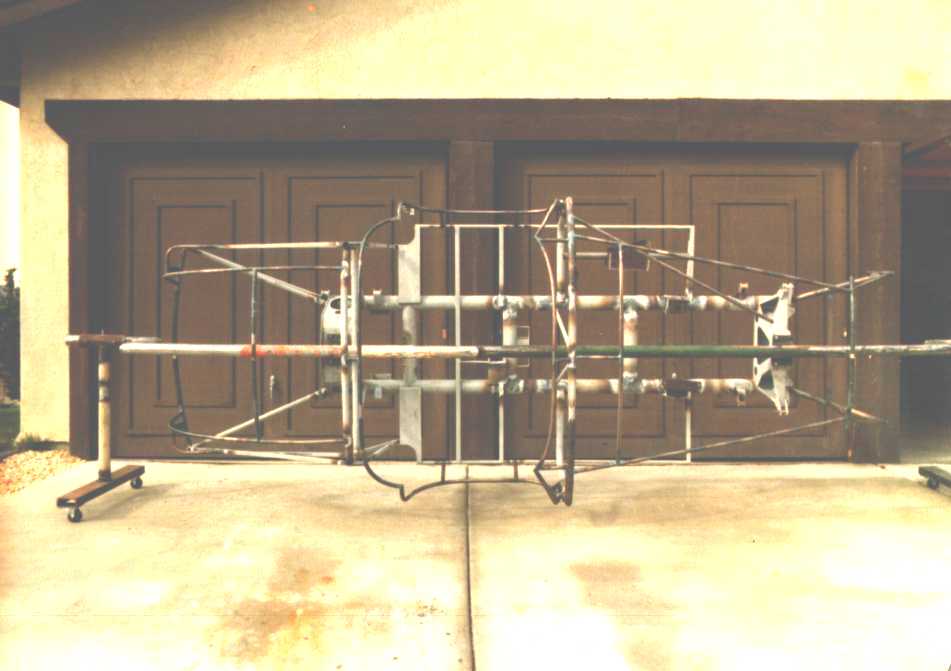
Chassis Rotisserie
A device, that although not necessary for Cobra work, certainly makes a lot of the chassis fabrication and painting work much easier is a Chassis Rotisseri.
There are obviously many ways to fabricate such a device, but the rotisseri described in the drawings below has been utilized for the construction my 289 Cobra and my Daytona Coupe replicas (both of which are based on chassis accurate to the originals). More recently, the rotisseri has been utilized during chassis repair work on a 1956 AC Ace chassis. Use on the Ace did require a minor bracket between the rotisseri and the AC frame because the road spring attachment bolts on the Ace were not easily removable.
In use, the rotisseri is bolted to the Cobra chassis on the front and rear spring towers. Obviously, the road springs must be removed from the chassis for the rotisseri to be mounted. The handle allows the chassis to be rotated with very little effort. The locking bolts on the end stands allow the chassis to be firmly held in any positon. The offsets in the main shaft allow the rotisseri to be used with the body mounted.
Click on the following "289 Chassis Rotisseri" text to download a PDF file.