Welcome to Our Garage
Daytona Coupe, 289 and 427 Cobras
-9-
Cobra Construction Drawings -
Examples
Overview of this "Examples" section
This section of the web site includes a few examples of the construction drawings that I have developed over the years. The original goal of the drawings was to document my Daytona for my own enjoyment. The "drawing process" actually became quite enjoyable and almost took on a life of its own as a part of my hobby.
I assigned each individual part on the car it's own unique part number then developed a drawing for each of these parts. The drawings have been drawn to scale in CAD and are as accurate as I can make them. There are untold hours of measuring, researching, refining and actual drawing of these Construction Drawings. To clarify, these drawings and their identification numbers are based strictly on measuring of acutal original Cobras and have no connection to any drawings that may have been originally developed by AC Cars, Shelby American or any of their suppliers.
Showing a few samples of these drawings seemed to be in order. Clicking on the drawing will link to a larger PDF version of the selected drawing. (Many of these example drawings have the dimensions disabled in the webite, for obvious reasons. The full drawing sets are completely dimensioned.)
Although the "drafting" began with the 289 Roadster, the initial drawings were done manually. About the time our roadster was competed, CAD (Computer Aided Drafting) software became availabe at reasonable cost. My manually created drawings were redone on the CAD software. Extensive rechecking of the drawings was done and where necessary drawings were revised and / or added.
I have selected a few typical drawings to show examples of the drawings that I have developed. the examples start with a few 289 Roadster drawings and following the progression similar to the maner in which the actual cars developed at Shelby American, they move into examples of the Daytona Coupe and finally to the 427 Cobra.
The last example drawings are recent additions to my drawing packages. The original Cobras utilized a number of cast parts on the cars. To attempt to round out my collection of drawings, I have tried to document a number of these cast parts.
Another, often overlooked, yet very significant requirement of any car is it's electrical system. The owners manuals for the 289 and 427 Cobras include wiring schematics. However, documention of the Daytona Coupe electrics are very elusive. My drawing of the Dayatona Coupe Electrical system provides complete details on the approach used in my Datyona and provide insight into how the original cars were wired.
289 Cobra Roadster Front Tower
The following drawing shows one of several detail views of the 289 Roadster front tower. This component is used to support the front transverse leaf spring and the upper end of the shock absorbers. Comparing this drawing with the example drawing of the 427 Cobra front tower (shown below) demonstrates one of the significant changes made as Shelby American progressed to the final evolution of the Cobra.
289 Roadster rear wheel arch:
The 289 Cobras utilized a rear wheel inner panel that was fabricated from aluminum. The panel is fabricated from several pieces and has a relatively complex shape. The following drawing includes some of the buck details for fabricating this part.
289 Cobra and Daytona Coupe Rear A-arm
As noted in other places of this web-site, the 289 roadsters (and therefore also the coupes) utilize a tubular steel A-arm as the lower suspension link combined with a transverse leaf spring (which forms the upper suspension link). One of the shortcomings of this design is the lack of adjustability of the wheel camber (without significant effort to modify the spring length). Over the years, there have been a number of Cobra owners that have solved this dilemma by modifying the stock A-arm to incorporate a Heim joint to allow the lower suspension link length (and hence the camber) to be more easily adjusted. The following drawing shows a stock 289 rear A-arm. I have seen several variations on the Heim joint modified A-arm and hope to develop a drawing showing a modified arm in the future.
Moving on to the Daytona Coupe Cobra
The example drawings now transision from the 289 Cobra Roadster to some that I have developed for the Daytona Cobra Coupe. The basic ladder chassis for the Daytona Cobras were fabricated in England by AC Cars, then shipped to Shelby American in Los Angles where the Shelby crew made the modifications required to convert the roadster chassis into a coupe version. (Only the first Coupe CSX2287 was completely built in Los Angles by the Shelby crew. Subsequent bodies were fabricated in Itally on the chassis modified by the Shelby American team in Los Angles.) In general, each coupe was unique and most had slightly different fabricating styles or designs for any particular subcomponent that the Shelby crew built (surprise, surprise; these were race cars and they were needed on the track ASAP.) Not being present in the shop as the cars were being fabricated, one can only speculate why there are differences; however, suffice it to say that each coupe is different.
Daytona accelerator pedal:
The following drawing shows some of the accelerator pedal details used on one of the coupes. Unlike the 289 roadsters which utilized an aluminum casting for the pedal and its housing, the coupes utilized a pedal fabricated from steel.

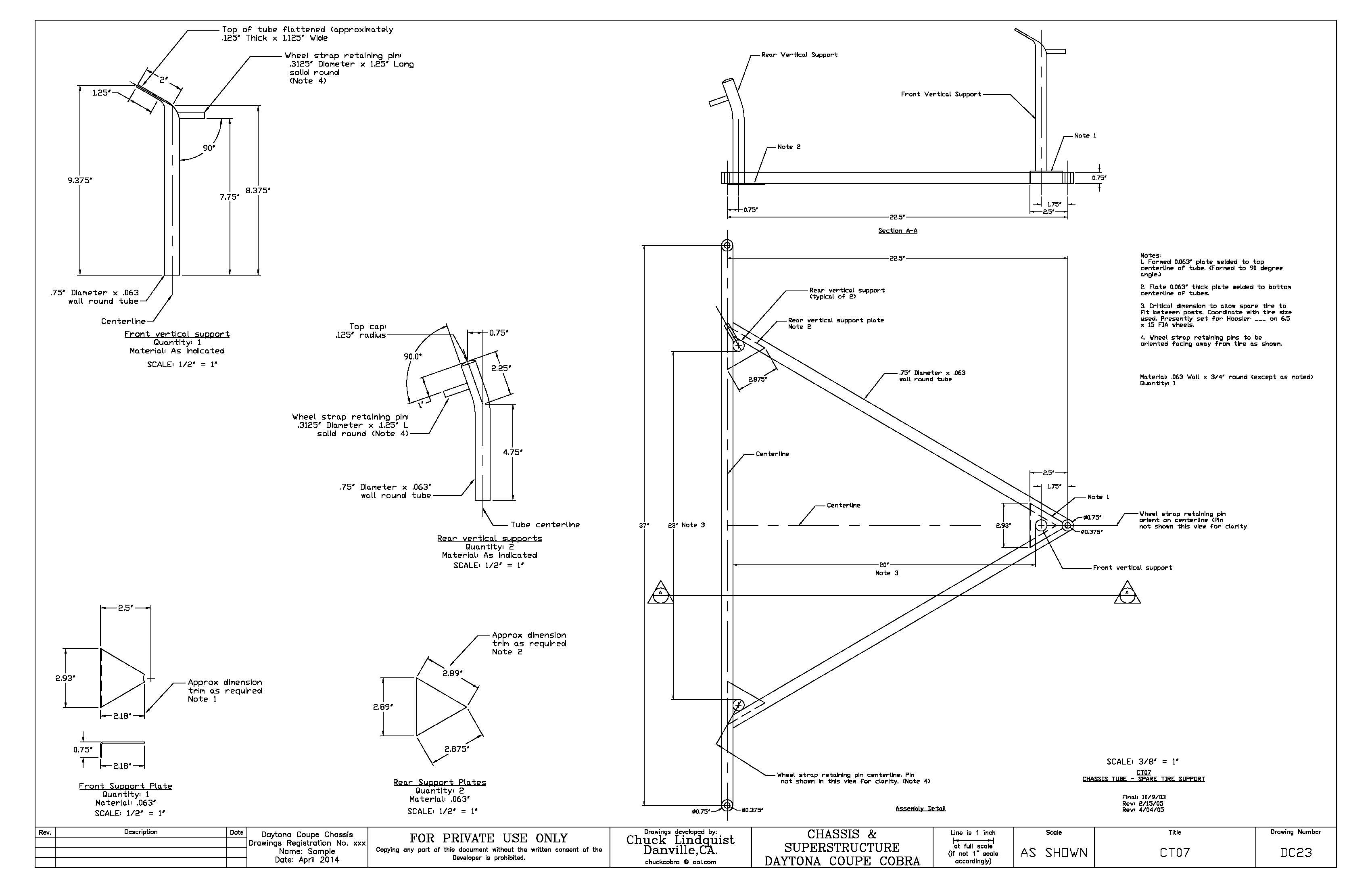
Daytona spare tire carrier:
Another interesting component on the Daytonas and probably recognizable by many Cobra enthusiasts is the manner in which the spare tire is mounted. The coupe's rear hatch was hinged to allow access to the area behind the seats and it was here that the spare tire was located. The floor in this area was only .050” thick aluminum so it was obviously not structurally adequate to support the tire. The solution was to build a tube frame adequate to support the tire independent of the floor. The following drawings show some of the details involved in the fabrication of this component of the coupe.
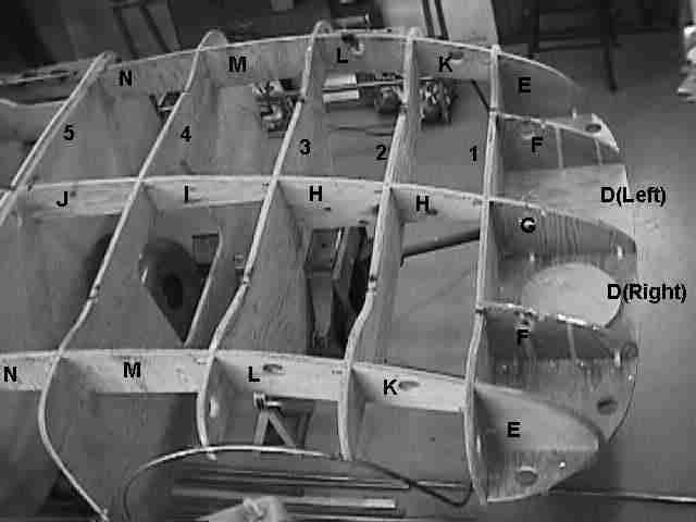
Daytona Body Buck:
As discussed in other portions of this website, one on the most time consuming tasks was to fabricate the buck on which the aluminum body skin was built. The complete buck is obviously the size of a completed car. As space in my shop became a premium, the buck needed to be disassembled to make way for other “stuff”. There are over 75 individual pieces of ¾” plywood that need to be screwed together to make up the complete buck. Just to make sure that it could be correctly re-assembled, I labeled each of the pieces. The following photo shows how I documented this aspect of the task for future reference.
Finally some 427 Cobra Examples
Another transision of these example drawings will be to show a one from the 427 Cobra set. As Shelby American's need for higher performance outgrew the capabilities of the 289 Cobra, the 427 Cobra came into being. As noted in other parts of this site, the 427 was a completely different animal than its predicessor. The following drawing examples provide a glimpse into only a few of the changes needed in the "new" cobra.
427 Cobra Front tower:
Finally, I got around to making drawings of the 427 Cobra roadster. Although the 427 inherits it body and many components from it's 289 parents, it is a completely different car. The 427 chassis and many of its component pieces, brackets and tubing are considerably more complicated (at least for this era of car chassis) than the 289 cars. The following drawing details the front tower for the 427 cars. Comparing it with the drawing above for the 289 Cobra is illustrates one of the major differences in the two chassis

Some Final General Drawing Examples
The last example drawings shown here are recent additions to my drawing packages. The original Cobras utilized a number of casting parts on the car. To attempt to round out my collection of drawings, I have tried to document a number of these cast parts. Another, often overlooked yet very significant requirement of any car is it's electrical system. The owners manuals for the 289 and 427 Cobras include wiring schematics. However, documention of the Daytona Coupe electrics are very elusive. My drawing of the Dayatona Coupe Electrical system provides complete details on the approach used in my Datyona and provide insight into how the original cars were wired.
289 Cobra Alternator Bracket
Although a standard Ford alternator bracket can be modified to work, the correct alternator bracket for the 289 Cobras is unique to this car. The original Cobra bracket moved the bottom mounting point of the alternator slightly further from the water pump pulley to provide clearance for the engine oil dip stick and increased fan belt adjustment distance. This drawing details the correct Cobra bracket.

Daytona Coupe wiring harness
One final example drawing is of the Daytona Coupe Cobra wiring harness. The drawing provides harness details that correspond to the wiring schematic also included in the Electrical System and Parts drawings. The object of the harness drawing is to take span the divide between the more conceptual wiring schematic to the more practical installation details. These wiring diagrames, although not a copy of an original Daytona, full details of my Coupe which utilizes correct component placement (based mostly on CSX2601) as well as period correct component list and race car born electrical system simplicity.